



A Load Cell Manufacturer and Your Source for
Weighing Systems & Instruments
Sourcing a weighing system from separate suppliers means matching a sensor to an amplifier to an instrument that were never designed to work together, and chasing several vendors when something needs support. The accuracy you actually get is only as good as the weakest link in that chain.
BLH Nobel removes that risk. As an experienced load cell manufacturer and a single source for weighing systems and instruments, we design and build every element of the chain in-house: load cells and weigh modules, force measurement sensors, process weighing instruments, custom solutions, and the calibration and service behind them. Each is engineered for the precision, robustness and longevity that industrial weighing and force measurement demands.
The result is one accountable partner, from a single load cell to a complete weighing system, with products field-proven in more than 100 countries and the hardest environments on earth.
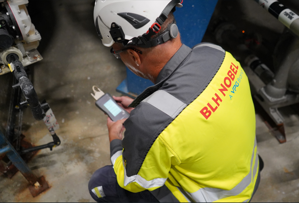
Why the Calibration Method Matters
Electronic weigh systems give process industries a non-intrusive, highly accurate, and reliable measure of mass inside a vessel or silo. Properly installed and calibrated systems routinely reach accuracies of 0.02% with a resolution of one part in 50,000, far better than typical level (0.5%) or flow (0.1%) measurement.
As quality programs and standards such as ISO 9000 raise the bar, it is no longer enough to calibrate accurately. The calibration also has to be documented and traceable. The right method is largely a function of the accuracy you need, the traceability you must prove, and, just as importantly, what is practical given the vessel, the budget, and the time available. A freestanding silo of low-cost material can be calibrated cost-effectively by electronic simulation, while an FDA-validated pharmaceutical reactor may need deadweights to full scale.
How the Measurement is Built
A weigh system uses several load cells to support the vessel, and their signals are combined into a single weight value in one of two ways.
- Analog summed system: the analog mV signals from each load cell are combined in a summing circuit into one averaged signal, then conditioned, digitized, and displayed by the indicator or transmitter.
- Digitally summed system: each load cell output is digitized individually, giving a known, calibrated value at every support point before the values are summed. This is what makes pushbutton and PROM calibration possible.
What Sets the Accuracy
Strain-gauge load cells are very linear and repeatable. A KIS load beam, for example, has a combined error around 0.02% of rated output and repeatability near 0.01%. System accuracy is then estimated by combining the individual error sources with the RMS method, a conservative predictor used for over 30 years. Beyond the components, installation decides the rest: attached piping can shunt load or add thrust forces, and uneven support deflection shifts load distribution. Good practice keeps support balanced within 20 to 30% across points and overall deflection under about half an inch.
Calibration Traceability to National Standards
Traceability links your measurement, through documented steps, back to a recognized national standard such as NIST. There are four levels, and total uncertainty is the RMS combination of every link in the chain.
- Level 1, national standards: the physical reference standards held at the national metrology institute.
- Level 2, primary standards: deadweight machines in controlled conditions and precision voltage standards.
- Level 3, secondary standards: portable deadweights, master bridges or load cell simulators, and voltage standards.
- Level 4, working standards: transfer standards in the field: calibrated load cells, DVMs, and portable calibrators.
Eight Ways to Calibrate a Weigh System
Electronic methods are fast and low cost but only verify the signal path. Physical methods take longer but also prove the mechanical behaviour of the installed system. They are listed below from simplest to most rigorous.
01Pushbutton / PROM (digital systems)0.05 to 0.5%Digitally summed systems with minimal piping
02mV simulation0.25 to 1.0%Uniform vessels with good load cells, lowest cost
03mV/V simulation0.10 to 1.0%Uniform vessels; ratiometric instruments
04Partial applied deadweight0.5 to 2.0%A quick slope check on almost any system
05Mass or volumetric flow0.25 to 1.0%Vessels that cannot take weights or applied force
06Hydraulic or mechanical force0.25 to 1.0%Systems with attachment points; proves the whole system (QuickCal)
07Full-scale build-up / substitution0.05 to 0.2%High accuracy when full deadweighting is impractical
08Full-scale deadweight0.02 to 0.1%Most certain; vessels that can take full weights
Case Histories
Case 1. mV/V calibration of inventory silos
Freestanding silos of self-leveling plastic pellets, too large for weights or build-up, but with minimal piping. An mV/V simulation was used with a 0.02% calibrator and load cells traceable to within 0.05%. The calibration accuracy was conservatively stated as 0.1%.
Case 2. Combination build-up and deadweight on a pharma reactor
An FDA-validated reactor with flexed piping needing better than 0.1%. A water build-up was taken to full, then deadweights brought it to full operating capacity, checked at more than 10 points. The displayed weight agreed within 0.05% of the applied deadweight, meeting the requirement.
Case 3. Mass flow calibration of a mix tank
A vessel with vertical and horizontal flexed pipes needing better than 1.5%. A certified mass flow meter (0.4%) calibrated the system to 66% of capacity over an electronic baseline, giving a combined accuracy better than 1.5%.
About this Handbook
This is a web summary of BLH Nobel Handbook TC0010, document 12223. The full handbook, with every step-by-step procedure, formula, and diagram, is available as a downloadable PDF. For traceable, accredited calibration performed by BLH Nobel, see the Calibration service.